The maximum current can be drawn is 700mA.

The Breadboard power supply has 3.3V/5V selectable output on two channels. XD-42 5V/3.3V Dual channel breadboard power supply.ģ.3V/5V Output MB102 Breadboard Power Supply Module Board - Overview.Onboard berg male header for GND, 5V, 3.3V outputĪlternative and compatible products for 3.3V/5V output MB102 Breadboard power supply module boards are listed below.Output current: Maximum output current 700mA.Output voltage: 5V, 3.3V (adjustable via jumpers.The pinout can be easily seen in the Board Legend. The power LED will notify the user of input power availability status. The module also offers a push switch to turn OFF and ON the entire power supply module.Īn additional feature is a USB input with two 5V, two 3.3V, and 4 GND pinout for additional power pin requirements. These power channels can be independently configured for 3.3V, 0V, and 5V operations. The board has two independent channels of power output for breadboards. Its ease of use allows users to connect any DC power supply unit that has 6.5-12 VDC power output from a barrel jack. And we will not obsolete the parts, they will be new parts to avoid problems with the obsoleting mechanism.The 3.3V/5V output MB102 Breadboard power supply module is an easy to use, most useful breadboard component that can be added with any breadboard related projects where 5V, 3.3V or both power requirements are required.

I have the fpz files, I just need the svgs. It would be great if you could fix the problems, homogenize all the parts (e.g., now the pulse and the ac power supplies have different circle diameters) and use the Fritzing conventions. I also made a pulse power supply, but it is based on the battery and it is rotated.

There is also an AC power supply (add a dc power supply and change it to AC), but this part does not align well vertically with the grid and connects not at the end of the connector: See also SCH DC Power: wires from the center of the connectors

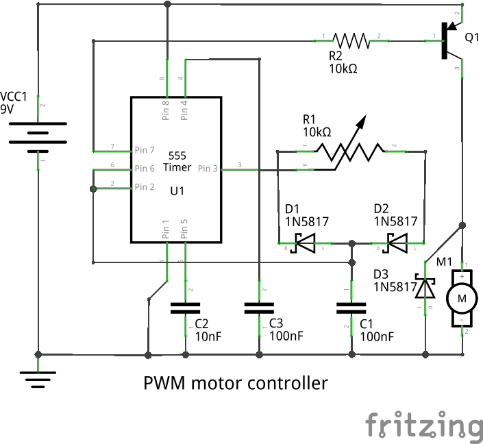
The DC power (sch part only) is not aligned with the grid correctly and has a problem with the wires connecting in the middle of the connectors. This forces to rotate the part (which is annoying for advanced users) or contributes to creating “ugly” schematics by beginners, see power supplies need to be oriented vertically The battery part in core is ok, but it is rotated 90 degrees, which is not the common way of writing electronics (power at the top and ground at the bottom). I could use your expertise with SVGs and Fritzing conventions if you are up to it. I am working on extending the simulator for transitory analysis and I realized that the different power supplies have some issues and they are very heterogeneous.


 0 kommentar(er)
